

")
Ceramic capacitors are extremely sensitive to mechanical stress. Even slight bending and especially torsional forces can quickly lead to cracks and subsequently to fires. Often, burning ceramic capacitors are underrated in the electronics industry although they may pose a substantial problem.
RoodMicrotec offers effective solutions for this problem. Find out more about how we deal with reasons and potential dangers and which methods we use to detect crack formations unequivocally.
Reasons for Burning Ceramic Capacitors
Ceramic capacitors may catch fire for various reasons. Mechanical stresses such as bending and torsional forces can cause cracks in the ceramic material, which may then lead to short circuits and overheating. Electrical overvoltage, inadequate heat dissipation, and poor solder connections are other common causes of burning ceramic capacitors.
Particularly ceramic capacitors that are soldered onto assemblies are susceptible to cracks. They can occur during mounting, depaneling or when fixing the assembly in the application, especially when the positioning of the capacitors on the assembly is not ideal.
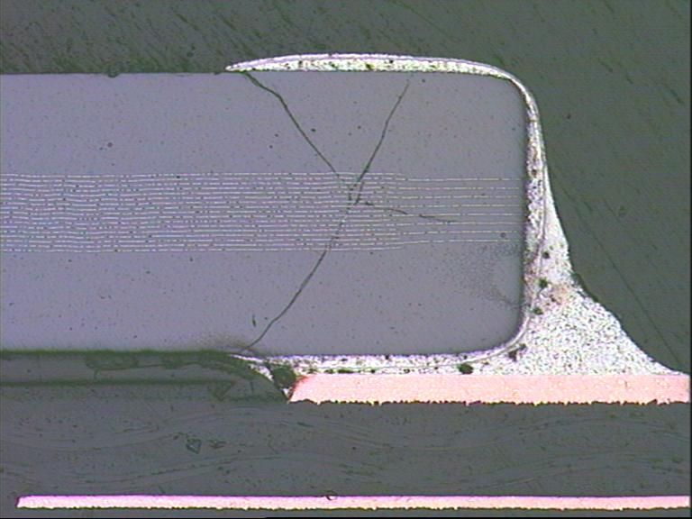
Cracking of ceramic capacitors typically starts at the edge of the solder joint on the bottom of the capacitor and runs slanted into the terminal cap.
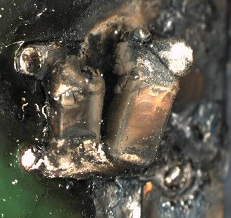
Within the application, the electrode material is at risk to spread along these cracks. As soon as two adjacent electrodes are connected, the ceramic capacitor turns into a resistor. If this resistor is low-ohmic and the energy source has enough power, this can lead to destruction and even fire.
Component manufacturers are aware of this issue. Standardized tests are carried out to characterize the sensitivity of the components. Here, the capacitors are soldered onto circuit boards and then bent. Cracks occur with a bending load between 3 and 5 mm when the fixing points are at a distance of 9 cm. Torsional loads are even more dangerous for the components. Here, cracks have already been detected from a torsional load of 0.5 mm per 9 cm. Unfortunately, this is not yet tested in a standardized way.
Dangers of Burning Ceramic Capacitors
The dangers of burning ceramic capacitors are numerous and varied. In addition to potential damage to the electronic circuit, fires can occur that may cause considerable damage to property and even personal injury. Especially in safety-critical applications such as aerospace or medical technology, burning ceramic capacitors can have devastating consequences.
Due to the fact that only around 1% of these capacitors with cracks are detected during the final electrical testing, many of them end up in use – and thus in our everyday lives! This poses a huge risk, as material can migrate while the assembly is in use. Ultimately, this can lead to short circuits in the capacitors, which not only causes a failure of the electrical assembly, but also leads to fire hazards.
Solutions and Preventive Measures
To minimize the risk of fires, various measures are required. These include the careful selection and quality testing of components, avoidance of excessive mechanical stress during the assembly, a proper heat dissipation, and the monitoring of operating conditions to prevent electrical overvoltages.
Regular inspections and tests help to identify potential problems at an early stage and to rectify them, if necessary. RoodMicrotec offers special testing procedures to detect cracks in ceramic capacitors timely and thus prevent failures.
Assembly designers should be aware of these correlations, as the risk can be minimized significantly with a suitable layout. In order to avoid risks during depaneling, it is recommended, e.g., to place ceramic capacitors always with a distance of at least 5 mm from the edge of the PCB. This requirement is often not feasible for small assemblies. However, this risk can at least be reduced by placing the capacitors such that the component axis runs parallel to the edge of the PCB. The respective type of separation (e.g. sawing instead of breaking) can also minimize the risk.
The same applies to bolt holes. As there is a latent risk of twisting when screwing, a sufficiently large distance should be chosen or the alignment should be such that the component axis runs along concentric circles around the opening.
In addition to the use of suitable layouts, it is advisable to back the reliability of the capacitors or assemblies by means of physical analyses. In the past, the most commonly used analysis technique was metallographic microsectioning. However, these microsections are very time-consuming, destructive and limited to one cross section plane. Due to the individual preparation, the examination is inevitably reduced to a few components. One advantage is that typical crack patterns – starting at the edge of the solder joint and running into the component cap – can be displayed very well. Nevertheless, selective analysis remains a problem. Since the threat to the components depends on the mounting position, this procedure does not guarantee that components most at risk are actually analyzed.
Unique Analysis Method
As an alternative, RoodMicrotec offers a test method in which the terminal metallization of the component is etched off and then subjected to an optical inspection. This ensures a clear detection, as cracks always occur on the surface of the component and are located at the edge of the terminal metallization.
Here, the capacitors are gently detached from the assembly. The subsequent etching of the terminal metallization is carried out by means of a wet-chemical etching process, which enables to treat all components simultaneously in one container. Inspection is then performed with a stereo microscope.
This process not only saves time, but also allows to prepare many or even all parts at the same time. Another advantage: the components will not be damaged and additional (3D) information can be obtained, which makes it possible to produce metallographic sections subsequently.
Furthermore, a significant advantage of this method is the possibility to infer mechanical stress from the position of the cracks. Cracks caused by bending stresses often run along the entire length of a connection. In the case of torsional stress, usually both connections are affected, with the cracks occurring at the opposite corners, respectively.
Summary
Burning ceramic capacitors are a serious danger that should not be underestimated. By identifying the causes, assessing potential hazards, and implementing appropriate solutions, companies and engineers can minimize the risk of fires and failures caused by ceramic capacitors. A comprehensive understanding of this problem is crucial to ensure the safety and reliability of electronic systems.
Are you interested in our failure analysis test services or a technology assessment? Contact us
Content Information

Editor: RoodMicrotec GmbH
Source: The text is based on information from RoodMicrotec GmbH.
Copyright: All images, videos and audio files published in this article are subject to copyright. Reproduction in whole or in part is not permitted without the written permission of RoodMicrotec GmbH.
For further information or inquiries about a joint cooperation, please contact